Usually, the first decision to be made when building a layout, is what size is it be? This is usually determined by the space available to site the layout. Most modellers are constrained by the availability of the space within their home, whilst others go to the lengths of purpose built accommodation. This can be a shed or an extension to the house. For me the decision was already made, in the form of the 8 x 4 existing base board. A decision in parallel with the base board size is the gauge size of the layout. Most modellers in the UK (including me) opt for OO Gauge (4mm:foot). For most of us that’s the scale of the models we see in toy and model shops. However, there are a variety of gauges, N which is half the size of OO, HO which is very similar in size to OO, but is considered to be a truer scale and others that are larger than OO. Once the choice of gauge has been made, the track layout should be determined prior to building the baseboard. This being necessary, to ensure point and signal motors, avoid areas supported by the base board frame. Also to produce a list of track parts needed to build the desired track layout. The serious modeller, who wishes to accurately model a particular branch line, station area or location, will take this into consideration in the size and shape of the base board(s), together with the track layout.
The era and railway company owning the modelled railway are a prime consideration. Is it pre 1948 when the UK railways were nationalised, is it British Railways, is it Continental or North American, or is it the modern era, with diesels, etc? This decision determines the locomotives and rolling stock to be purchased or scratch built, the style of the buildings, signalling systems, etc. Most of us have to make some of the decisions based purely on cost. The larger the gauge the higher the cost and the greater the space required to accommodate the model. If we decide to build a DCC layout then we generally have to accept higher cost over a normal DC system.
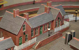
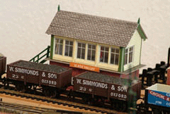
For myself the most decisions were simple at the time, it had to be based on the London Midland and Scottish Railway, but the era would be 1930’s to late 1950’s. This was the railway company I grew up with and the era which would give me most flexibility in locos and livery. The location was to be a fictitious complex near Kettering, which I named Slade Valley. Slade Valley actually exists, through which runs the River Slade, but has never had a railway station. The nearest railway stations are Kettering (still operational), Rushton and Desborough which were closed, with Desborough Station being demolished (all on the Midland Main Line). All of the DCC equipment is from ZTC Controls Ltd, an English company based in Glastonbury, Somerset. Most of the buildings including the Signal Boxes are card kits from Metcalfe Toys & Models, augmented with card from cereal boxes.
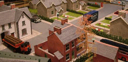
Where am I with the model? Well at the present time (early May 2005), after starting in May 2003, returning to part time work in December 2003, then retiring for the third time in January 2005, the layout is complete with regard to the track work, signalling (which is 2 Aspect Coloured Light), station buildings (which due to their position on the layout, I am a little unhappy with), railway workers housing and amenities such as the village pub and shop, telephone box, post box, bus shelter and working street lights are completed. All the buildings have working internal lighting. Much of the scenic work needs to be completed, such as the track ballasting. The track ballasting is something I am not looking forward to doing.
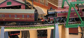
The layout is based on a modified Hornby double oval layout, with a passing loop on the inner oval, which is a figure of 8 with flyover track. The outer oval has extensive sidings to house out of use carriages and wagons. Which is a recent addition and are accommodated on a 5 x 1 foot extension fixed to the side of the original base board. From the inner oval there is access to the 2 Road Locomotive Shed (large enough to stable 2 tender locomotives) and the Goods Shed. There is access to a Locomotive Shed Siding, from the outer oval for stabling additional locomotives. From the outer oval there is access to a Programming Track, for Loco Decoder configuration.
As ever, new ventures bring the opportunity to learn from mistakes. I had my share with this modelling project.
If I am honest, given the learning curve and the mistakes made during the building process, I would like to start the project right from scratch. This is due to the fact I did not plot the path from it origin to its ultimate destination, thus the project was more an iterative process rather than a planned operation. If I do take the decision to break down the layout and start again, it will certainly involve a new base board and track layout. While compromise was always needed in modelling the layout, I believe I compromised too greatly in using the existing base board and utilising most of the track from the original 125 Train Pack. The consequence of this has been bad electrical continuity on the track and derailments, due to poor point work. The point work was a real problem and despite replacing most of the original point work with new sections from the same manufacturer (they had supposedly modified the design), problems still persisted. Only after replacing once again with sections from a different manufacture, were the problems solved. Equally, using the original base board also brought space and aesthetic problems, with the need to use surface mounted Point Motors (yes you are right, some motors needed to be in areas occupied by the base board frame work).
At this point, I will move on from the problems and say (with all honesty), that despite these mistakes and misjudgements, solving them brought much pleasure and satisfaction. The whole experience thus far, though at times frustrating, has been great. The inclusion of an old laptop PC, providing background sound affects complements a sound decoder and increases the degree of realism.
Having thoroughly enjoyed building and operating this layout, in January 2007, I made the decision to move to the larger 'O' Gauge (7mm:foot or 1/43rd scale). Therefore, this layout will be dismantled and the process of building the new layout will commence. The project will be the subject of a new article to be included in this section of the website.


